+91 44 26251279 / 26257859
89, Sidco Industrial Est, Ambattur, Chennai - 600098

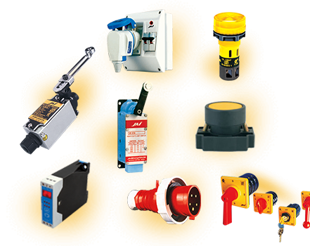
JAIBALAJI JW Series Limit Switches are in Great demand owing to their sophistication and the marks of ISI, CSA and CE. Manufactured on the basis of latest concepts in switching technology, JAIBALAJI switches are guaranteed for greater reliability in performance.
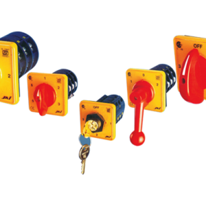
Made to suit various circuits of multi-pole and multi positions, JAIBALAJI switches enable easy hand operation. JAIBALAJI Cam operated Rotary switches are designed for ONLOAD switching and assembled on add-n-block system and are used for various application.
Download Product Catalogue PDF
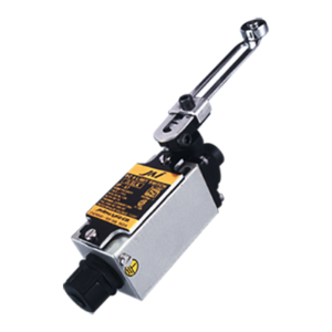
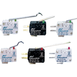
PLUNGER TYPE SWITCHES SHOULD BE USED WHERE A MICROMETER ADJUSTMENT OF THE PLUNGER IS REQUIRED. THESE SWITCHES ARE SUITABLE FOR USE ON MACHINES WHERE SHORT, CONTROLLED CAM MOVEMENTS ARE PRESENT. OPERATION MUST BE IN LINE WITH PLUNGER AXIS OR CAN BE PERPENDICULAR TO THE PLUNGER AXIS ON THE ROLLER PLUNGER TYPES.
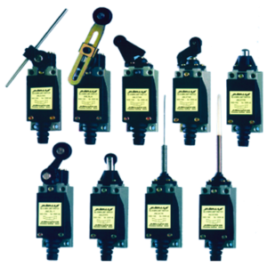
Non Plug-in Small Precision Limit Switches are designed specifically for use on modern machine tools, to control starting, stopping or reversing of electrical motors including safety and signalling light, lifting gear, hoists, conveyors, etc.
The two pole limit switches are identical in appearance and size to the popular single pole version. Two pole limit switches are desirable in many installations and can reduce the number of limit switches and control relays used.
Protected against oil, cutting lubricants and fine dust penetration by using compressed rubber rings, special gaskets, pressure die cast zinc top and aluminium bottom cover.
All the parts are ant-corrosive material and paints.
Spring return, Snap action, Quick make and Quick break contacts.
| AC 15 rating | Single pole 1 NO + 1 NC Changeover contacts |
Double pole 2 NO + 2 NC Changeover contacts |
| 110 V 240 V 440 V 600 V |
4 A 2 A 1 A 0.8 A |
3.0 A 1.5 A 0.8 A 0.6 A |
| DC 13 rating | Single throw | Double throw | Single throw | Double throw |
| 115 V 230 V 600 V |
2.0 A 0.5 A 0.1 A |
0.5 A 0.2 A 0.02 A |
1.0 A 0.3 A 0.1 A |
0.2 A 0.1 A |
 |
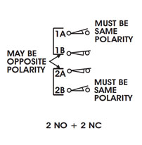 |
1 N.O.1 N.C. contacts are Single Pole, Double Throw one circuit normally open and one circuit normally closed. These circuits are electrically separate, but cannot be used on opposite polarities.
Operating Data for types JO1 and JO2
Capacity:
|
 |
|

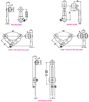
APPROXIMATE DIMENSIONS NOT FOR CONSTRUCTION (Dimensions in mm)
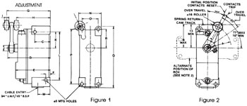
Figure 1 and 2 JW-12, JW-18
| A | B | C | D | E | F | G | H | I | J | K | L | M | N | O | P | Q | R |
| Length of Arm 5 mm |
Arm Length Plus 5 mm |
24 | 68 | 56 | 5 | 68 – 70 |
56 – 58 |
8 | 11 | 23 | 78 | 19 | 37 | 27 | 89 | 98 | 29 |
OPERATING TORQUE 3.16 Kg Cm Repeat Accuracy + 0.025 with 35 mm arm.
NOTE 1: For reverse operation place arm and roller in similar position to left of centre line and reverse position of return spring.
NOTE 2: If roller is used in dotted position (side view) it will not pass over cover, and unit must be mounted accordingly.
APPROXIMATE DIMENSIONS NOT FOR CONSTRUCTION (Dimensions in mm)
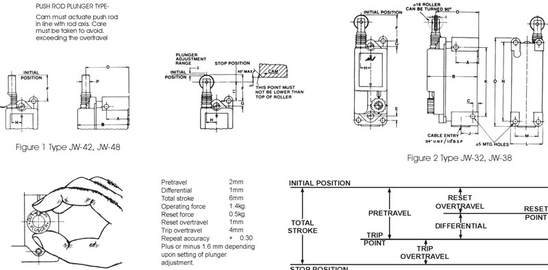
Figures 1 & 2 types JW-32, JW-38, JW-42, JW-48
| Type | A | B | C | D | E | F | G | H | I | J | K | L | M | N | O | P |
| JW-32, JW-38 JW-42, JW-48 |
24 | 56 | 5 | 46 | 5 | 28 | 6 | 10 | 3 | 19 | 78 | 37 | 27 | 89 | 98 | 8 |