Inductive Proximity Switches

FEATURES
  • REF : STANDARD IEC 947-5-2
  • REVERSE POLARITY PROTECTION
  • SHORT CIRCUIT PROTECTION
  • OVERLOAD PROTECTION
  • FALSE PULSE DURING
  • POWER ON/OFF PROTECTION
  • NOISE SUPPRESSION

Download Product Catalogue PDF

Available in store

Choose Quantity
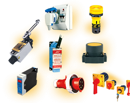
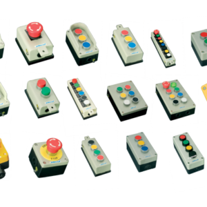
Inductive Proximity switches are used to identify the presence of metal objects, speed measurments, position sensing, counting etc., without any physical contact with the objects. It enhances the durability of the switch and ensures maintenance free work.

Inductive Proximity switch generates high frequency alternating field at the active face by the oscillator circuit. When any metal object is brought into the field it causes oscillation to stop. Hence the demodulated voltage feeding the trigger disappears.

   DC Inductive Proximity Switches:
   For DC switches the trigger operates rapidly when oscillation stops. This
trigger switches the O/P, NPN/PNP transitor to drive an electronic circuit
or relay.

APPLICATIONS

•     AUTOMOBILE INDUSTRIES
•     STEEL INDUSTRIES
•     PACKAGING INDUSTRIES
•     METAL HANDLING EQUIPMENT
•     PROCESS AUTOMATION
•     CNC / NC MACHINES
•     CONVEYOR EQUIPMENT ETC.,
   AC Inductive Proximity Switches:
   For AC switches a thyristor is triggered when oscillation stops. This thyristor
i s connected in series with a bridge and this series combination is connected
to the    AC load.
DC SWITCHES SPECIFICATIONS
Reference: STANDARD : IEC 947-5-2
   Nominal Voltage    10 – 30 VDC
   Voltage Drop    0.8 – 7 V*
   Load Current    300 mA *
   No Load Current    10 – 20 mA *
   Switching Frequency    200 HZ **
   Ambient Temperature    -25° C To +60° C
   Hsyteresis    <15%
   Sensing Distance Tolerance    ±10%
AC SWITCHES SPECIFICATIONS
Reference: STANDARD : IEC 947-5-2
   Nominal Voltage    90 – 250 VAC
   Voltage Drop    8 V
   Load Current    500 mA Max
   No Load Current    5 mA
   Switching Frequency    15 HZ Max **
   Ambient Temperature    -25° C To +60° C
   Hsyteresis    <15%
   Sensing Distance Tolerance    ±10%
Specification Varies depending on Switch Type.
Specification Varies depending on Switch Size & Range.

CONNECTION DIAGRAM FOR DC SWITCHES


CONNECTION DIAGRAM FOR AC SWITCHES

TECHNICAL SPECIFICATIONS

MODEL HOUSING FLUSH /
NON-FLUSH
MOUNTING
THREAD
L1 L2 L3 NUT ELECTRICAL
TYPE
LED SENSING
DISTANCE Sn
TYPE OF
PROTECTION
JB 8 M F 8X1 35 60 14 PN 1 IP 67
JB 8 S L 8X1 40 65 14 PN 1.5 IP 67
JB 12 M L 12X1 45 65 5 17 PN 4 IP 67
JB 12 M F 12X1 55 75 17 PN 2 IP 67
JB 12 S L 12X1 50 70 3 17 PN 4 IP 67
JB 18 S L 18X1 55 75 7 24 TPNBA 8 IP 67
JB 18 M L 18X1 50 70 7 24 TPNBA 8 IP 67
JB 18 M F 18X1 55 75 24 TPNBA 5 IP 67
JB 30 S L 30X1.5 55 75 12 36 TPNBA 15 IP 67
JB 30 M L 30X1.5 45 65 12 36 TPNBA 15 IP 67
JB 30 M F 30X1.5 55 75 36 TPNBA 10 IP 67
JB 36 M L 36X1.5 45 65 20 44 TPNBA 20 IP 67
JB 36 M F 36X1.5 45 65 44 TPNBA 15 IP 67
JB 50 M L 50X1.5 40 60 16 57 TPNBA 25 IP 67
JB 50 M F 50X1.5 40 60 57 TPNBA 20 IP 67
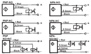
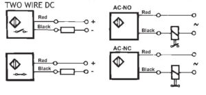
(NOTE :- STANDARD WIRE LENGTH PROVIDED – 2 MTS ONLY)

M-METAL    10 – 30 VDC
S-SYNTHETIC
F-FLUSH
L-NON-FLUSH
P-PNP P1 – PNP NO
N-NPN P2 – PNP NC
N1 – NPN NO
N2 – NPN NC
PN-THREE WIRE DC
T-TWO WIRE DC T1 – 2 WIRE NO
T2 – 2 WIRE NC
B-FOUR WIRE DC (NO + NC) B1 – PNP NO + NC
B2 – NPN NO + NC
A-TWO WIRE AC A1 – AC NO
A2 – AC NC

ORDERING CODE

FLUSH MOUNTING IN METAL

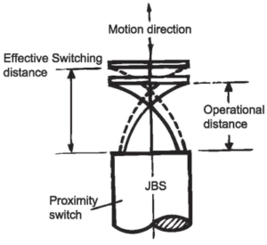
A proximity switch can be flush mounted in metal if it can be surrounded by metal up to the level of the active face, without changing its present characteristics. In order to avoid interference when mounting side by side, a spacing distance, corresponding to the diameter of the switch must be maintained.

NON FLUSH MOUNTING

A proximity switch can be flush mounted in metal if zone is required for maintaining the characteristic values of the switch. A clear zone of 3x the diameter of the sensing surface should be maintained.

EFFECTIVE SWITCHING DISTANCE

It is the switching distance when voltage and temperature can be at any value within the rating of the switch and this will be between 81 & 121% of switching distance.

OPERATIONAL DISTANCE

It is the distance at which the operation of the proximity switch, under stated temperature and voltage conditions is guaranteed within O and 81% of the nominal switching distance.
SOME IMPORTANT CORRECTION FACTORS

WHEN TARGET MATERIAL IS NOT STEEL

Chrome – nickel
Brass
Aluminium
Copper
approx. 0.9 x Sn
approx. 0.5 x Sn
approx. 0.4 x Sn
approx. 0.4 x Sn

Our other products include Photo Electronic Sensors, Capacitive Proximiti Switches, Reed Maganetic Switches, Limit Switches, Rotary Switches & Telescopic Brush Plugs. Special types of switches available on request.

There are no reviews yet.

Be the first to review “Inductive Proximity Switches”